


Vibration Shaker Open-Loop Alarm: Causes and Troubleshooting Guide
In the world of environmental testing and precision equipment, two challenges consistently cause downtime and unexpected costs: vibration shaker open-loop alarms during operation, and transport damage to sensitive test chambers and shakers during delivery. While they occur at different stages of the equipment lifecycle, both share a common root cause—a lack of controlled, verifiable checkpoints. This article provides a practical, scenario-based approach to solving both pain points, helping lab managers and engineers reduce risk and improve equipment reliability.
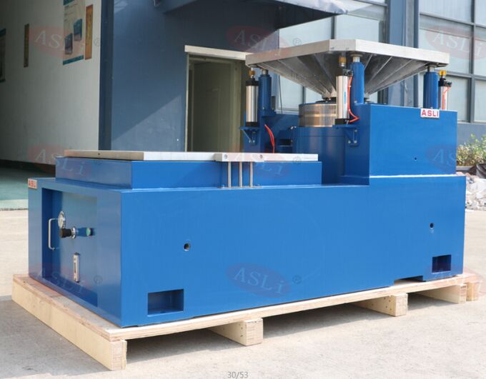
Pain Point 1: Vibration Shaker Open-Loop Alarms – From Panic to Systematic Diagnosis
An open-loop alarm is not a random failure; it is the controller telling you that the control loop has been broken. The controller sends a small drive signal to the amplifier and expects a corresponding response from the accelerometer on the shaker table. If the response falls below a preset threshold, the system stops to protect the shaker and the test article from uncontrolled motion. The real customer pain is not the alarm itself, but the uncertainty: Where exactly is the loop broken, and how do I fix it quickly without replacing expensive parts?
Understand the Signal Path
The control loop flows through: Controller output → Drive cable → Amplifier → Shaker → Accelerometer → Input cable → Controller feedback. An open-loop alarm means this chain is interrupted somewhere. Instead of random guessing, isolate the problem by following the signal path in reverse order—from the easiest component to separate to the most complex.
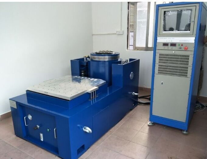
Step-by-Step Isolation Procedure
- Controller + Drive Cable Self-Loop Test: Disconnect the shaker and amplifier. Use a drive cable to directly connect the controller's
INPUTport to itsDRIVEport. Run a low-level sine self-loop test (e.g., 100 mV/g sensitivity). If the alarm clears, the controller and that cable are healthy. If the alarm persists, swap in a known-good drive cable and retry. Still failing? The controller may have an internal fault. Common cable issues include broken connectors, loose solder joints, or short circuits between the core and shield—check with a multimeter. - Accelerometer + Input Cable: Switch to preview mode and open the time-domain signal window. Gently tap the shaker table with your hand. A healthy system will show a clear impact waveform synchronized with your taps. No waveform? Try a known-good accelerometer and input cable. For IEPE sensors, verify a DC bias voltage of approximately 24 V between the BNC center pin and shield in preview mode. No bias voltage indicates a sensor or power supply issue.
- Amplifier + Shaker: Confirm the amplifier gain is turned up and not set too low for the mass of the test article. To verify the drive side, keep the controller in self-loop mode, feed the drive signal into the amplifier input via a tee connector, and slowly increase the gain. The shaker table should vibrate. If it does not, the issue lies in the amplifier or shaker—contact the manufacturer's service team.
- Test Settings – The "False Open-Loop" Trap: Sometimes the alarm is triggered by settings, not hardware. If the pre-test level is set too low (below the system's noise floor), or the upper limit voltage for the closed-loop check is too small for a heavy test article, the system may misinterpret normal noise as an open loop. The solution is to increase the pre-test starting voltage or level so the valid signal rises above the noise floor. Caution: Never bypass the protection logic by drastically increasing gain or the closed-loop limit—this risks damaging the shaker.
Preventive Measures
Regularly perform self-loop tests to verify controller and cable health. Label and manage accelerometers and cables to prevent channel mix-ups. Always perform a tap-test preview before critical tests. Train operators to follow the sequence: check connections → check settings → adjust gain last.
Pain Point 2: Safe Transport of Precision Test Equipment – From "Hope for the Best" to "Controlled Delivery"
Transporting temperature-humidity chambers, vibration shakers, and other precision instruments involves more than avoiding a drop. These devices are highly sensitive to external vibration and shock. Even if the exterior looks perfect, internal sensors, optical modules, or calibration structures may have shifted slightly—problems that only surface during installation and commissioning, when accountability and remedies become difficult. Multi-modal transport (air, sea, road) subjects equipment to a mix of high-frequency vibration, low-frequency sway, and irregular road shocks, which generic packaging cannot handle. This is a primary source of hidden damage.
Three-Layer Protection Strategy
Effective transport protection is not about "more padding"; it is a three-layer defense: packaging isolates the environment → securing eliminates movement → process controls handling.
- Layer 1: Packaging – Shock, Moisture, and Compliance. Use plywood crates at least 15 mm thick and compliant with ISPM-15 (the international phytosanitary standard for wood packaging). Non-compliant crates may be detained by customs. Custom-cut high-density foam or EPE pearl cotton fills all gaps to prevent shifting. Wrap the equipment in moisture-barrier aluminum foil or PE film with desiccant—critical for sea freight to prevent salt fog and condensation. For temperature-humidity chambers with refrigeration systems, secure doors with tape, support piping to avoid cantilever stress, and consider applying thread-locking compound to electrical terminals or adding vibration-damping pads to relays.
- Layer 2: Securing – Zero Movement Inside and Outside the Crate. Bolt the equipment to a pallet or crate base and lock the casters. Inside the transport vehicle, use professional strapping to secure the crate to the vehicle's tie-down points, choosing reinforced base or frame locations—never apply pressure to panels or thin walls. For complete test chambers, adding a reinforced base frame and fixing the entire unit to a custom wooden pallet is a common manufacturer practice.
- Layer 3: Transport and Handling – Control Attitude, Shock, and Exposure. Temperature-humidity chambers must remain upright at all times; tilting generally must not exceed 30° (some models require ≤15°). Inversion can cause compressor oil to enter the refrigeration circuit, leading to liquid slugging and damage. Transport vehicles should be equipped with vibration damping; for long distances, add damping pads under the equipment. For short-distance moves of highly sensitive equipment within a facility, air-caster pallet trucks can reduce vibration input. In winter, allow the equipment to sit indoors for at least 24 hours before powering on to avoid condensation damage; in summer, protect from direct sunlight to prevent coating degradation.
Receiving Inspection Checklist – The Final Safeguard
Transport safety does not end with a signature on the delivery receipt. A proper receiving process should verify: external packaging for damage or water stains → after unpacking, inspect for dents or scratches → confirm all accessories (manual, certificate, spare parts) are present → allow sufficient resting time as specified before powering on → perform a no-load functional check. For precision test equipment, this step exposes any hidden deviations while the responsibility chain is still clear.

Common Logic: Checkpoints Beat Crisis Management
| Aspect | Vibration Shaker Open-Loop Alarm | Precision Equipment Transport |
|---|---|---|
| Nature of Problem | Control loop interruption during operation | Hidden damage during delivery |
| Core Strategy | Reverse isolation along the signal path; avoid blind part replacement | Layered blocking; keep vibration, moisture, and movement away from the equipment |
| Most Overlooked Step | Self-loop test and tap-test preview | Resting period after arrival and no-load verification |
| Shared Principle | Set verifiable checkpoints at critical nodes instead of tracing problems after they occur. | |
By implementing these scenario-based solutions, laboratories and manufacturers can reduce unplanned downtime, protect valuable equipment, and ensure that every test run starts from a known, reliable state. For further assistance with vibration shaker troubleshooting or custom transport packaging for temperature-humidity chambers, contact our technical team for a tailored inspection and logistics plan.